This tutorial provides an introduction to the basics of piezoelectricity. This includes an introduction to the nature of piezoelectricity, and a description of the two main families of piezoceramic materials (hard doped and soft doped). In this tutorial, you will also be introduced to the constitutive equations as well as the properties of piezoceramic material at high field. You will also find a description of the thermal properties of piezoceramic material, as well as an overview helping you select a ceramic material.
Nature of Piezoelectricity
The piezoelectric effect was discovered by Jacques and Pierre Curie in 1880. The initial observation was the appearance of dielectric charge on a crystal proportional to an applied mechanical stress. Soon thereafter, the converse effect i.e. the geometrical strain of a crystal proportional to an applied electrical field, was discovered.
Basics on piezoelectric material
Piezoelectricity is the property of some materials to develop electric charge on their surface when mechanical stress is exerted on them. An applied electrical field produces a linearly proportional strain in these materials. The electrical response to mechanical stimulation is called the direct piezoelectric effect, and the mechanical response to electrical simulation is called the converse piezoelectric effect.
Different piezoelectric materials
Piezoelectric effect is exhibited by most of the materials that possess a non-centrosymmetric crystal structure. Some naturally occurring crystalline materials possessing these properties are quartz and tourmaline. Some artificially produced piezoelectric crystals are Rochelle salt, ammonium dihydrogen phosphate and lithium sulphate. Another class of materials possessing these properties is piezoelectric ceramics.
In contrast to the naturally occurring piezoelectric crystals, piezoelectric ceramics are of a “polycrystalline” structure. The most commonly produced piezoelectric ceramics are lead zirconate titanate (PZT), barium titanate and lead titanate. Polycrystalline ceramic materials have several advantages over single crystal piezoelectric materials, including the ease of fabrication and forming of various shapes and sizes. In contrast, single crystals must be cut along certain crystallographic directions, limiting the possible geometric shapes, but offer superior piezoelectric properties, except Curie and phase transition temperatures.
CTS Piezoelectric Products
PZT crystal structure
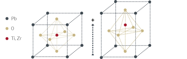
PZT has crystal structures belonging to the perovskite family with the general formula AB03. In the following figure, the ideal, cubic perovskite structure is shown. PZT crystallites are centro-symmetric cubic (isotropic) above the Curie temperature and exhibit tetragonal symmetry (anisotropic structure) below the Curie temperature.
Poling process
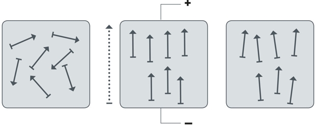
Piezoelectric ceramics consist of grains (crystallites), each of these grains contains domains that are randomly oriented before poling, as shown in the left figure below. As a result, the net polarization of the material is zero and therefore ceramic does not exhibit piezoelectric properties. During poling process, adequate DC electrical field is applied and this applied electric field orients the domains in the electric field direction (as seen in the middle figure below) and lead to a remanent polarization of the material (as seen in the right figure below).
Hard and Soft Piezoceramic Material
Although there are several types of piezoelectric ceramic materials available today, most can be placed into one of two general categories: “Hard” or “Soft” PZT materials. The perovskite structure is very tolerant to element substitution (doping) – therefore the terms “hard” and “soft” are used. Even small amounts of a dopant (~1%) may cause substantial changes in the properties of a material.
Characteristics of hard piezoceramic material
Hard piezoelectric ceramics have higher mechanical quality factor and are suitable for dynamic/on-resonance applications. Since higher mechanical quality factor provides more efficient energy conversion (from electrical to work), hard materials can withstand high level of electrical excitation and mechanical stress, generate less heat during this process and are not easy poled or depoled except at elevated temperature. Compared to soft piezoelectric materials, hard piezoelectric materials lack the strain because of the lower d coefficients.
Characteristics of soft piezoceramic material
Soft piezoelectric ceramics have higher piezoelectric coefficients compared to hard piezoelectric ceramics, at the expense of quality factor. Soft piezoelectric ceramics also provide higher sensitivity and permittivity and are well suited for static or semi static applications, where large strain is required. Soft piezoelectric ceramics, when operated in dynamic mode at high field suffer from high dielectric losses and low quality factors, which may lead to overheating over an extended period of operation.
Below you can see a comparison of the characteristics of the hard and soft doped piezoceramic material.
| Type of ceramic |
Soft piezoceramic material |
Hard piezoceramic material |
Piezo constants
(strain in static) |
High |
Low |
Dielectric constants
(capacitance) |
High |
Low |
Dielectric losses
(self-heating) |
High |
Low |
Coercive field
(depolarization) |
Low |
High |
Quality factors
(strain at resonance) |
Low |
High |
CTS Ceramic Material Properties
Constitutive Equations
Because of the anisotropic nature of piezoelectric ceramics, properties vary depending on direction. To identify directions in a piezoelectric ceramic element, a specific coordinate system is used. Three axes are defined, termed 1, 2, and 3, analogous to X, Y, and Z of the classical three-dimensional orthogonal set of axes.
Piezoelectric coefficients and directions
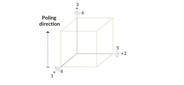
The polar, or 3 axis, is determined by the direction of the poling. Unless the component needs to be utilized in shear mode, electric field is applied in direction 3. Directions 1 and 2 are physically equivalent so they can be defined arbitrarily, perpendicular to direction 3 and to each other. The directions termed 4, 5 and 6 correspond to tilting (shear) motions around axes 1, 2 and 3 respectively.
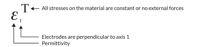
In shear mode, after poling, electrodes are stripped and redeposited perpendicular to axis 1. In this case, once electric field is applied, the component shears in one dimension without any change in other dimensions.
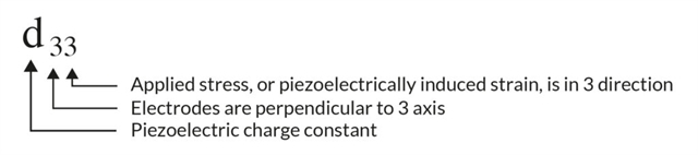
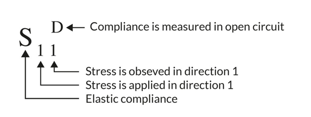
Piezoelectric materials can be characterized by several coefficients. Piezoelectric coefficients with double subscripts link electrical and mechanical quantities. The first subscript provides the direction of the electric field, or the dielectric charge produced. The second subscript provides the direction of the mechanical stress or strain.
The piezoelectric constants relating the mechanical strain produced by an applied electric field are termed the piezoelectric deformation constants, or the “d” coefficients. They are expressed in meters per volt [m/V]. Conversely, these coefficients which are also called piezoelectric charge constants may be viewed as relating the charge collected on the electrodes to the applied mechanical stress. The units can therefore also be expressed in Coulombs per Newton [C/N].
In addition, several piezoelectric material constants may be written with a “superscript” which specifies either a mechanical or an electrical boundary condition. The superscripts are T, E, D, and S, signifying:
- T=constant stress=mechanically free
- E=constant field=short circuit
- D=constant electrical displacement=open circuit
- S=constant strain=mechanically clamped
Here are three examples of parameters used in the piezoelectric equations together with an explanation of their notation:
Fundamental piezoelectric equations
There are different ways of writing the fundamental equations of the piezoelectric materials, depending on which variables are of interest. The two most common forms are (the superscript t stands for matrix-transpose):
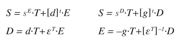
These matrix relationships are widely used for finite element modelling. For analytical approaches, in general only some of the relationships are useful so the problem can be further simplified. For example this relationship, extracted from line 3 of the first matrix equation, describes strain in direction 3 as a function of stress and field.
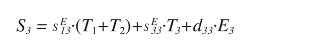
Just like any other elastic material, strain is proportional to the applied stress. But in addition for piezoelectric materials, an additional piezoelectric term is present, relating strain to electric field also.
Limitations of the linear constitutive equations
There are a number of limitations of the linear constitutive equations. The piezoelectric effect is actually non-linear in nature due to hysteresis and creep.
Furthermore, the dynamics of the material are not described by the linear constitutive equations. Piezoelectric coefficients are temperature dependent. Piezoelectric coefficients show a strong electric field dependency.
Properties of Piezoceramic Material at High Field
Piezoelectric materials exhibit non-linearity, hysteresis and creep. This section provides typical material data to understand and compensate these effects.
Linearity: Actuators (individual and stacked multilayer) and benders
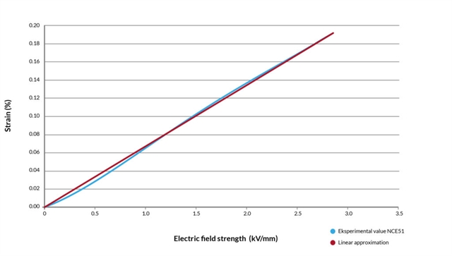
The stroke versus applied voltage relationship for piezo electric actuators is not perfectly linear as predicted by the piezoelectric equations. Typical performances are shown in the following figures. As it can be seen, the extension vs voltage curve is actually slightly S-shaped. At low voltage, the curve for increasing voltage is concave upward and the shape is close to quadratic.
The example below shows the displacement during charging of an actuator using the piezoelectric material NCE57. Higher resolution curves can be found in the “hysteresis” section. Non-linearity implies that stroke at 1kV/mm is less than expected from the linear extrapolation using stroke at the maximum recommended field (which corresponds to 3kV/mm).
Very high electric field material data: Actuators (individual and and stacked multilayer) and benders
In some applications, it is desirable to archive maximum strain from the piezo electric element only by applying a very high electric field. In some cases the maximum recommended field strength of 3kV/mm may be exceeded e.g. for short-term use applications or static applications. Operating field of 4kV/mm is normally acceptable, however testing is recommended.
The figure below shows how strain evolves with electric field for our different materials up to a maximum electrical field strength of 9kV/mm. The drawback of applying a very high electric field is that the actuator lifetime is reduced drastically.
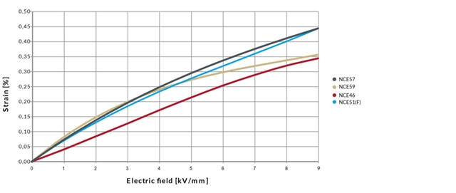
The data in the figure are only of informative character and we recommend to contact our R&D before designing actuators based on very high electric field.
Linearity: Shear plates
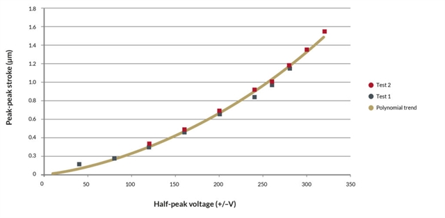
The peak to peak stroke versus peak applied voltage relationship for shear plates is not linear. Typical measurements are shown in the following figure. As it can be seen, the displacement increases when the actuator is used close to the maximum recommended voltage.
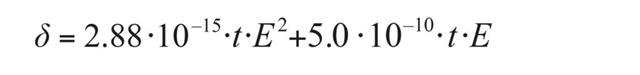
The polynomial trend follows the experimental relationship. With d being the displacement, t the height of the actuator and E the applied electric field (Voltage/height):
Hysteresis: Actuators (individual and stacked multilayer) and benders
All piezoelectric materials exhibit a mechanical hysteresis as the strain does not follow the same track upon charging and discharging. The hysteresis is expressed as the maximum difference between the two tracks divided by the maximum strain, as can be seen in the figure below. Hysteresis tends to decrease with ageing. If hysteresis is a problem for a specific application, it is common to use a model-based compensation or a feedback loop to compensate it. Feedback signal can be position, force or dielectric charge.
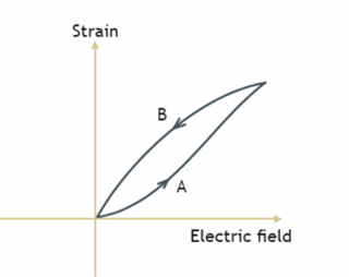
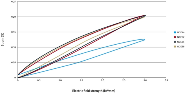
The hysteresis depends on the type of ceramics and the amplitude of the input signal and can vary from 13% to 20%.
| Material |
Hysteresis (%) |
| NCE46 |
20 |
| NCE51/51F |
19 |
| NCE57 |
19 |
| NCE59 |
13 |
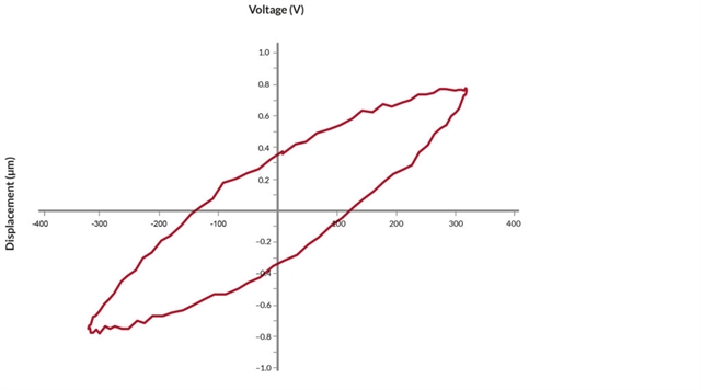
On bending actuators the same hysteresis is present. However, because of the push-pull configuration, it has a symmetrical shape.
Hysteresis: Shear plates
Due to their high non-linearity, shear plates exhibit much higher hysteresis than other actuator types. Hysteresis at full voltage amplitude is in the order of 35%. Reducing the amplitude of the voltage will reduce hysteresis.
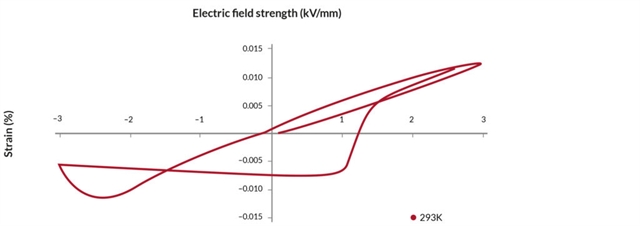
Operation under reverse bias: Actuators (individual and stacked multilayer) and benders
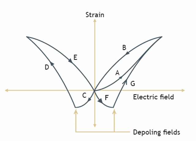
In addition to the normal hysteresis curve AB when the applied voltage is positive, the butterfly diagram CDEFG defines the behavior of the material through a complete cycle of positive and negative operating electric fields. Negative electric fields produce negative strain along curve C until the depoling field (coercive field) where the extension suddenly turns positive following the curve D. The process is repeated along curves EFG when the electric field is made positive again. The “butterfly” diagram provides a complete characterization of the depoling and repoling process.
Most hard piezoelectric materials can only be fully poled or depoled at elevated temperatures so once poled, they can tolerate high reverse fields without difficulty.
We do not recommend operation under reverse field for quasi-static actuators. However, in some applications this can bring some additional strain. The drawbacks are the lower linearity, increased hysteresis and losses. In addition, temperature must be monitored as the coercive field varies with temperature (refer to “thermal properties”).
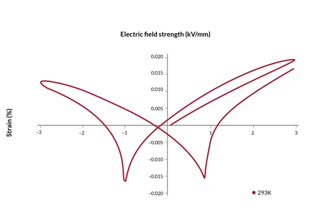
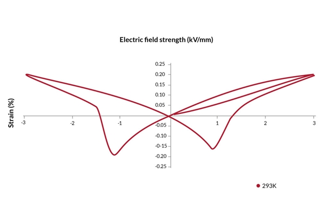
Soft piezoelectric materials are easily depoled when subjected to an electrical field opposite to the poling direction. The effect of cycling between positive and negative voltages for various piezoelectric materials is shown in the following figures:

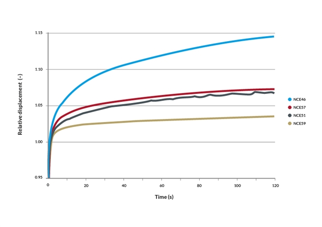
Creep
Piezoelectric materials exhibit a creep effect i.e. the material continues to expand for some time upon application of voltage. Correspondingly the material does not immediately return to the initial strain level after return to 0V. While creeping, the material continues to draw charge at very low levels. The creep effect for different actuator materials is compared in the following figure, where the maximum electric field is established after 1s, corresponding to the baseline for displacement (relative displacement = 1).
Creep always occurs in the same direction as the dimensional change produced by the voltage step. The effect is logarithmic so the additional expansion between 10s and 100s will be similar to the expansion obtained between 1s and 10s. For linear/stacked actuators, typical values are 4% per decade when using the piezoelectric material NCE51/51F and 9% per decade when using NCE46. Values are 2-3 times higher for bending actuators. Creep is related to the long-time average that the actuator has experienced in its life.
Thermal Properties of Piezoceramic Material
The electrical and piezoelectric properties are affected by temperature variations. Each piezoelectric material is affected differently by temperature changes, according to the method of manufacture and chemical composition of the material.
Maximum temperature
Piezoelectric materials should be used below the Curie temperature to avoid depoling. Rule of thumb is half Curie temperature. If the temperature were to that raise close to the Curie temperature or above, it will cause the piezoelectric material to become partially or completely depoled and severely degrade the performance. For applications that require operation at elevated temperature a material with a sufficiently high Curie temperature must be chosen. Maximum recommended operating temperatures are specified for each product. It is important to monitor temperature, in particular for dynamic applications, where the component can heat-up during operation due to internal dissipation.
Minimum temperature
Our multilayer products can be used at cryogenic temperatures and have been demonstrated down to 4mK. For these applications a specific preparation (wires, adhesive etc.) is required.
The mechanical and electrical properties of piezoelectric ceramic are greatly reduced at cryogenic temperatures. When piezoelectric actuators are cooled down to cryogenic temperatures, the piezoelectric ceramic behaves like a very hard piezoelectric material featuring:
- Strong reduction of electrical capacitance
- Reduction of loss factor
- Reduced strain coefficients d33 and d31
- Major improvement of the coercive field.
Improvement of the coercive field at low temperature enables a piezoelectric actuator to become extremely stable against electrical depoling. Therefore, a much wider bipolar operation compared to room temperature is possible. Therefore, drop in strain coefficient at low temperatures can be partially compensated for.
Below is an example of cryogenic measurements at two different temperatures showing the relationship between stroke (displacement) and voltage. As it can be seen, the stroke at 77 K is approximately reduced to half the value at room temperature. Due to the strong increase of the coercive field, it can also be observed that the actuator exhibits a fairly linear voltage-displacement characteristic at negative voltage. The piezoelectric actuator becomes extremely stable against electrical depoling and the loss in stroke at low temperature can be partially compensated by using a wide bipolar operation.
A more problematic parameter is the thermal expansion coefficient for ceramics, important to consider when designing devices where piezoelectric actuators will be part of a composite structure and where the other elements of constructions are e.g metals. The thermal expansion coefficient for ceramics is similar to many ceramics and glasses and is typically in the range of 10-5 meter/meter °C to 10-6 meter/meter °C. A major difference with common materials is that the thermal expansion coefficient is anisotropic with respect to the poling direction.


How to Choose a Piezoceramic Material
The table below gives an overview of the characteristics of two different piezoceramic materials.
| |
Soft piezoceramic material
(NCE56) |
Soft piezoceramic material
(NCE51) |
Hard piezoceramic material
(NCE46) |
| NCE46 |
++ |
++ |
– |
| NCE51/51F |
+ |
– |
– |
| NCE57 |
+ |
– |
– – |
| NCE59 |
– |
+ |
++ |
| |
– |
– |
++ |
| |
– |
– |
++ |
| |
– |
++ |
++ |
The range goes from — to ++, where — is low, and ++ is high.