How Does a Piezoelectric Sensor Work?

How Does a Piezoelectric Sensor work?
 Piezoelectric sensors utilize the direct piezoelectric effect to convert a mechanical input into an electric signal. While the majority of piezoelectric sensors are based on the direct effect, some also exploit the converse effect as is the case with resonant piezoelectric sensors.
Sensors using the direct piezoelectric effect
Through the direct piezoelectric effect, several mechanical quantities can be measured, including force and torque, strain, pressure, acceleration and acoustic emission. Typically, such piezoelectric sensors are less suitable for low-frequency signals due to charge dissipation. As a rule of thumb, 10 Hz can be considered as the minimum frequency for piezoelectric ceramics [cf. Philips, 1991, p.20 c.2]. The upper frequency limit is generally given by the natural frequency of the piezoelectric sensor, which in turn is determined by the design.
Sensors for force, torque, strain and pressure
It follows directly from the basic piezoelectric equations that a piezoelectric element will produce a charge when a force is applied parallel to the direction of polarization. For a poled piezoelectric ceramic, the charge Q is proportional to the input
force F according to the following equation
Q = d33F
where d33 is the piezoelectric charge coefficient.
Alternatively, a flexure mode design may be used for certain piezoelectric sensors, in which case a so-called bimorph element within the sensor is deflected by the input force. The bimorph element consists of two piezoelectric plates, either poled in opposite directions (series configuration) or in the same direction (parallel configuration).
Reaction torque sensors may also rely on the piezoelectric effect, using several shear-mode piezoelectric elements, whereas torque measurements on rotating shafts typically are done with strain gauges [Gautschi, 2002, p.105].
Piezoelectric strain sensors can be seen as force sensors with a design that emphasizes strain [Gautschi, 2002, p.127]. They have the important advantage over strain gauges that they are very well suited for dynamical measurements [Gautschi, 2002, p.128]. Most of these sensors are intended for measuring internal strain, longitudinal or transverse, and are designed as so-called strain pins to be inserted in a bore [Gautschi, 2002, pp.130-135]. However, a few piezoelectric sensors measuring surface strain also exist [Gautschi, 2002, pp.128-130].
Similarly, pressure sensors are a special case of force sensors, generally using a membrane with a well-defined area [Gautschi, 2002, p.141]. It is common to classify these sensors according to the measured pressure, with low-pressure sensors measuring up to a few bar, and high-pressure sensors for pressures above 1 kbar. Piezoelectric sensors for extremely small pressure variations in the range of μbar are called piezoelectric microphones or – for underwater applications – piezoelectric hydrophones [Gautschi, 2002, pp.142, 146].
Often quartz is the piezoelectric material used in sensors intended for measuring force, torque, strain and pressure, especially when high stability and/or quasi-static measurements are important [Gautschi, 2002, pp.93-165], but piezoelectric ceramics may also be chosen for a handful of these sensor types to take advantage of the superior charge output and shaping possibilities inherent to the piezoelectric ceramic.
Acceleration sensors and acoustic emmission sensors
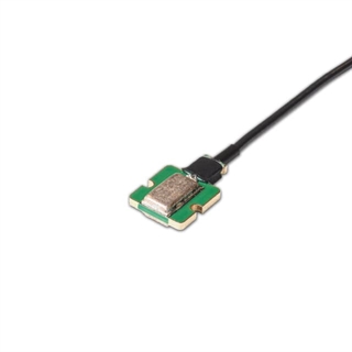
A sensor for measuring acceleration is called an accelerometer and can be seen as a force sensor with a mass attached to it [Gautschi, 2002, p.167]. In its simplest form, a piezoelectric accelerometer consists of a thin piezoelectric element with polarization perpendicular to the main surface, clamped between a so-called seismic mass or proof mass and a base plate. For vibrations parallel to the polarization, the force acting upon the piezoelectric element is given by Newton’s second law of motion and will generate a proportional charge as shown earlier. Such a piezoelectric sensor is a basic example of a compression-mode accelerometer, but often a design with several stacked rings held together by a center bolt and connected in parallel is used, especially if the piezoelectric material is based on piezoelectric crystals with low charge output, such as quartz or tourmaline. Like in the case of force sensors, flexure mode may be chosen instead of compression mode, in which case a bimorph element is suitable.
Many piezoelectric accelerometers are based on excitation in yet another mode, the shear mode. In one type of piezoelectric sensor design, a piezoceramic shear tube is mounted on a central stud with a tubular seismic mass around it. Other designs use one or several piezoelectric shear plates, each with a seismic mass attached. For accelerometers based on piezoelectric ceramics, it is especially relevant to use the shear mode, since the output signal could otherwise be disturbed by pyroelectric charges when the temperature changes. Piezoelectric ceramics such as PZT generally show a considerable pyroelectric effect with the generated field parallel to the poling direction. Since in shear elements the charge is collected perpendicular to the poling direction, this is a very convenient way of avoiding pyroelectric charges.
For accelerometers operating up to around 250 °C, soft PZT types like Pz23 and Pz27 may be used for the piezoelectric element, whereas for high-temperature applications special compositions based on bismuth titanates are available, e.g., Pz46 and Pz48.
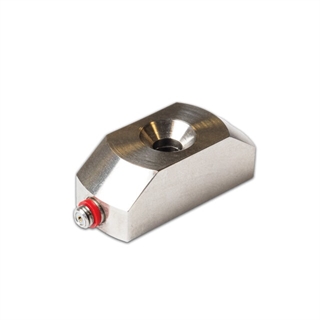
Acoustic emission (AE) sensors are used to detect signals transmitted through solids, for example in materials testing. They are closely related to the accelerometer type of piezoelectric sensors with the important difference that they do not need a seismic mass [Gautschi, 2002, p.201]. Instead, it is important to ensure good acoustic coupling to the test object which may be obtained by applying a thin layer of coupling liquid or adhesive. Very different frequency ranges are used in studies of acoustic emission, ranging from a few hertz in micro-earthquake studies to the megahertz range in AE examination of metals [Kalyanasundaram et al., 2007].
Sensors using the converse piezoelectric effect
Although the direct piezoelectric effect is the obvious choice for the majority of piezoelectric sensors, certain sensors rely on the converse piezoelectric effect (sometimes called the inverse or reverse effect), i.e., the generation of strain in response to an applied electric field. In a quartz microbalance, an ultrasonic resonator is kept in vibration at a specific frequency, typically in the megahertz range. In most cases, the generated wave is a standing shear wave. The resonance frequency is mainly determined by the geometry of the piezoelectric element (often a quartz crystal) and other components of the mechanical system, but it turns out that it is affected by even small changes of mass. Due to the high mechanical quality factor Qm of quartz (in the range of 106), very small frequency shifts can be detected, which may result in a weighing resolution below 1 μg/cm2.
References
Gautschi, G. (2002): Piezoelectric Sensorics,(Springer Verlag) Ch. 6-10.
Waanders, J.W. (1991): Piezoelectric Ceramics – Properties and Applications,
(N.V. Philips’ Gloeilampenfabrieken, Eindhoven, The Netherlands) Ch. 4.
Kalyanasundaram, P., Mukopadhyay, C.K., & Subba Rao, S.V. (2007): Practical Acoustic Emission,
(Alpha Science).
September 12, 2024


