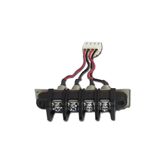
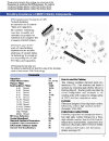
Filter Terminal Blocks
Recognized by UL, the CTS filtered terminal blocks are specifically designed to save time and money for EMI filtering applications. By combining a filtering component with an industry standard terminal block, CTS has created an effective barrier to EMI noise. CTS' filtered terminal blocks allow the engineer to eliminate EMI using an existing mechanical design concept.
CTS' commitment to excellence and service allows for customization of the filtered terminal blocks to meet your specific EMC qualifications. Backed by decades of ceramic component production experience, CTS filtered terminal blocks will meet or exceed your demanding application requirements.
Features & Benefits
- Saves Labor and Space
- Consistent Panel Layout
- Solves EMI Problems
- Meets Specific Requirements
- Filter Integral to Block
- Industry Standard Block
- Wide Range of Performance
- Customization
Reach out to us with any questions.
We're happy to help.

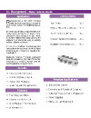
- Specifications
- Applications
- Popular Products
- Technical Resources
This specification describes the basic performance requirements of CTS Filtered Terminal Blocks.
Capacitance
- Measurement Conditions: Capacitance measured at 25°± 2°C, 50% max R.H. and Frequency of 1 KHz @ 1± 0.2VRMS.
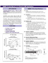
Insertion Loss
- Measurement Conditions: Insertion Loss values listed are measured in a 50Ω system at 25°C± 2°C under no-load conditions.
- Insertion Loss: The listed Insertion Loss values are typical for 500 and 600 styles under indicated conditions.
- Listed Insertion Loss data is a measurement of filter performance in a matched 50Ω system. It is highly recommended that filter performance be verified under actual circuit operation conditions.
Operating Conditions
Filters are designed to operate continuously at the voltage and current stated for each TUSONIX part number. If the operating ambient temperature is significantly higher than 25°C, the terminal blocks should be installed in equipment and tested under actual conditions to ensure that maximum temperatures are not exceeded.
Dielectric Withstanding Voltage
Filters shall withstand the specified voltage applied between the screw terminal and ground plane for one minute. Surge current shall be limited to a maximum of 50mA.
Insulation Resistance
Measured at 25°C± 2°C with 100VDC and charging current limited to 50mA max. the IR, after two minutes, maximum applications of the test voltage, shall be a minimum of 10,000 Megohms.
- Telecommunications
- Computer and Peripheral Equipment
- Industrial Process Control Equipment
- Power Supplies
- Office and Lab Equipment

Results Updated, 6 Results.
Skip to Filters
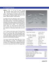
Filters
clear all

Where to Buy
CTS components are stocked and sold through a global network of distributors & sales representatives. Select your preferred partner in the link below.