Mounting Piezoelectric Actuators
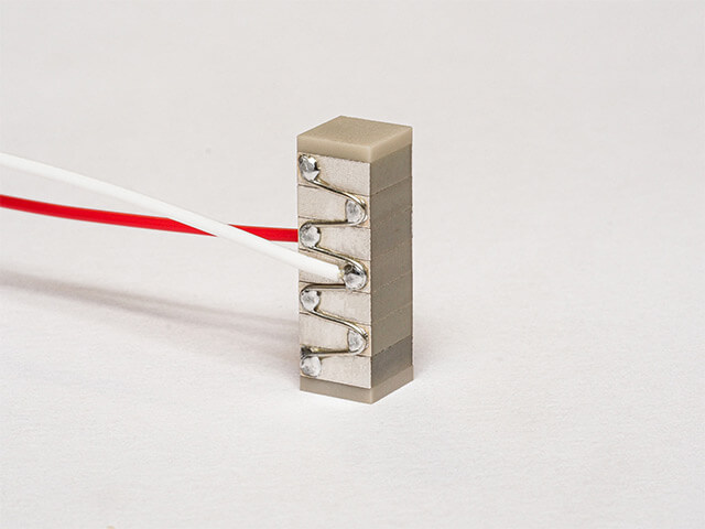
Linear Actuators
Linear actuators are ground on top and bottom surfaces (perpendicular to the direction of expansion) as a standard in order to obtain flat and parallel surfaces for mounting. The actuators may be mounted either by mechanical clamping or with an adhesive.
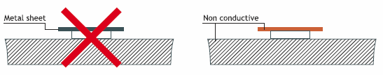
When assembling it is important to stay clear from the surface electrodes in order to avoid arcing and short-circuit. Avoiding short circuit can be achieved by:
- Making sure that there is a sufficient distance between the electrodes and any conductive surface. The safe distance depends on the environment and voltage rating and can be in the range 0.1 to 1mm.
- Adding an insulator, for example polyimide tape on any conductive surface near the electrodes.
- Having inactive ceramic plates between the actuator and the opposing structure.
For linear actuators, it is recommended not to use a metal plate on top and bottom in order to avoid short circuit.
Stacked actuators are manufactured as a standard with 1mm top and bottom insulating ceramic end-plates which ensure two functions: Electrical insulation and better repartition of the load.
For clamping, most materials can be used, although materials with a high stiffness (steel, titanium) are preferred in order not to affect the overall stiffness of the system, i.e. its force generation capability. The substrate must be clean, flat (<10µm depending on dimensions) and smooth (Ra 1.6µm). The clamping force must be adapted to the load on the actuator. While unloaded actuators can safely be used in static conditions without preload, for lightly loaded, low dynamic applications we recommend to apply 5MPa clamping pressure. For heavily loaded systems, higher pressures are required, typically 20MPa, sometimes up to 40MPa. When applying a force, be aware that the piezoelectric actuator will generate charge (i.e. voltage) during loading/unloading, so it must be connected to a resistor or shorted at all times.
The stiffness of the clamping mechanism in the actuation direction shall be as low as possible, typically under 1/10th of the stiffness of the actuator, in order not to hinder the movement of the actuator. Refer to our tutorials about quasi-static actuator applications for more information about the behavior of actuators under load.
For bonding, we recommend to use a semi-hard epoxy (Shore D 55-70) with a low viscosity (200-500 cPs). It is important to ensure a very thin glue line between the actuator and the substrate. To that effect, apply pressure, e.g. 2-5 MPa during the curing process. When curing at elevated temperature, be aware that the piezoelectric actuator will generate charge (i.e. voltage) during temperature changes, so it must be connected to a resistor or shorted at all times.
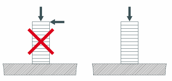
To avoid significant loss of performance, the mounting of the actuators should avoid mechanical clamping and/or bonding on the sides of the actuator.
The actuators may only be stressed axially. Tilting and shearing forces must be avoided.
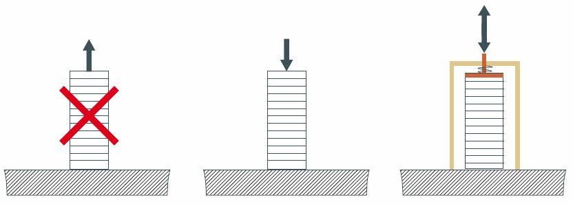
Actuators without preload are sensitive to tensile stress. Pulling forces can be caused by the load on the actuator or by inertial load, i.e. deceleration of the own mass of the actuator. It is recommended to apply a pre-load in order to protect the actuators from tensile stress. In addition, preloading will increase the stiffness of the actuator and thereby optimize its dynamic performance.
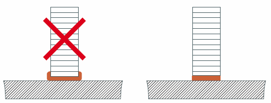
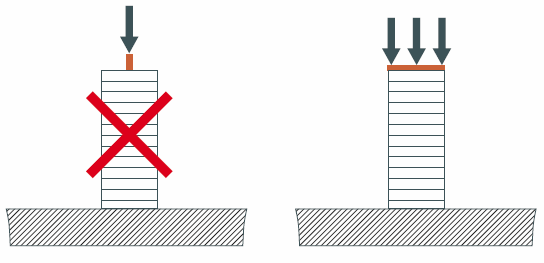
 The load must be applied on the full surface of the actuator in order to assure a good load distribution. Uneven loading can cause stress concentrations, leading to cracking. If this is not possible, an interface part must be used to help spread the load.
 During manufacturing or handling, minor chips on the end-plates can appear. Minor chips (<5% of the edge size) cannot be avoided, but such chips do not affect performance. Larger chips can cause stress concentrations and initiate cracking under heavy loads.
Learn more about our linear actuators
Bending Actuators
Plate Benders
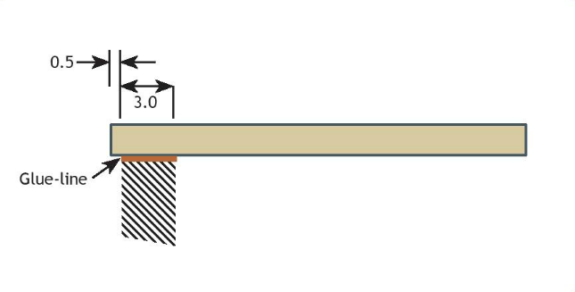
Bending plate actuators may be mounted either by mechanical clamping or with an adhesive. In all cases, make sure that there is a sufficient distance or insulation layer between the external electrodes and any conductive material.
Bending plate actuators are not ground on top and bottom surfaces and as such may have small variations in the surface. For this reason, a mechanical clamping should be done with moderate force, approximately 5 times the specified blocking force. The clamping force should be adapted to react the bending moment generated by the load on the actuator. It is recommended to use a relatively soft material for the substrate, such as polymers, composites or aluminum. Hard materials may generate stress concentrations leading to cracking.
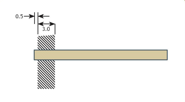 For bonding, we recommend to use a hard epoxy (Shore D 70-90) with a high viscosity (1000 cPs). Apply some pressure (0.2-1N) to ensure a thin glue line. It should be emphasized, that the gluing contact surface is restricted to cover only the inactive part of the bender in order not to reduce the stroke of the bender. Also, be aware that cure at high temperature may generate residual stress due to the differential thermal expansion with the substrate and may lead to unwanted curvature, particularly for thin benders and substrates. When curing at elevated temperature, the piezoelectric actuator will generate charge (i.e. voltage) during temperature changes, so it must be connected to a resistor or shorted at all times.
Ring Benders
Bending ring actuators may be mounted either by mechanical clamping or with an adhesive. In all cases, make sure that there is a sufficient distance or insulation layer between the external electrodes and any conductive material.
Important remark:
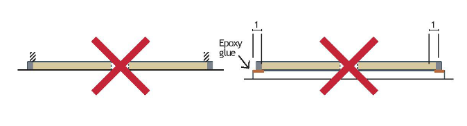
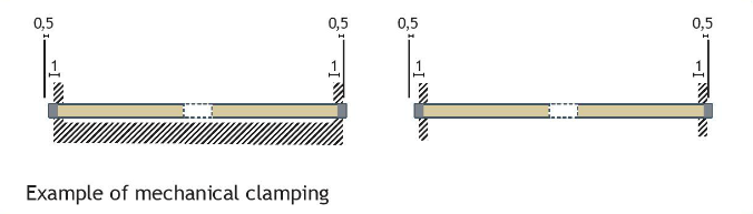
When actuated, ring benders deform into a cup shape. It is important to ensure that they are free to deform, i.e. that they are pinned (hinged) and not fixed along the outer diameter, otherwise their displacement will be reduced. For the same reason, ring benders should not be mounted against a large surface but only held at the outer and inner diameter. Flexibility can be introduced by limiting the width of the contact ring (max. 1mm) or by using soft materials and compliant structures for the substrate.
 Bending plate actuators are not ground on top and bottom surfaces and as such may have small variations in the surface. The mechanical clamping should be done with moderate force, as low as possible to avoid unwanted clamping which would reduce the maximum stroke. It is recommended to use a relatively soft material for the substrate, such as polymers, composites or aluminum. Hard materials may generate stress concentrations leading to cracking.
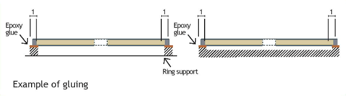
 For bonding, we recommend to use a semi-hard epoxy (Shore D 55-70). Apply some pressure (0.2-1N) to ensure a thin glue line. The width of the bond line should be limited (<1.5mm) to avoid constraining the motion. When curing at elevated temperature, be aware that the piezoelectric actuator will generate charge (i.e. voltage) during temperature changes, so it must be connected to a resistor or shorted at all times.
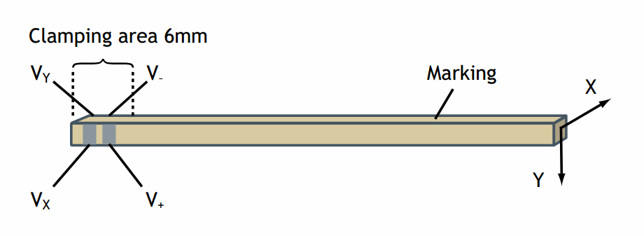
2D Benders
NAC2710
NAC2710 benders can be mounted in a way similar to bending plate actuators. The particularities are the clamping length of 6mm and the presence of electrodes on the side. Care must be taken not to short-circuit the electrodes.
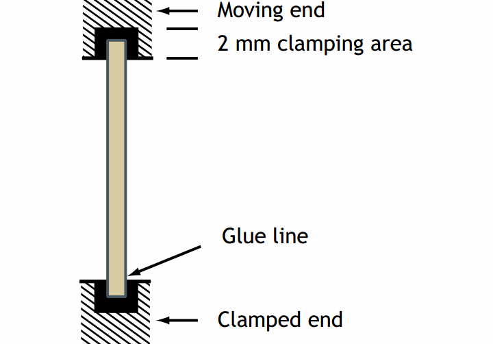
 NAC2810
NAC2810 benders can be mounted in a way similar to bending plate actuators. The particularity is the clamping length of 2mm at each end.
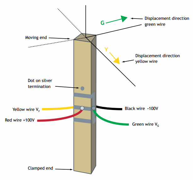
NAC2910
NAC2910 benders can be mounted in a way similar to bending plate actuators. The particularity is the clamping length of 2mm at each end.
Learn more about our bending actuators
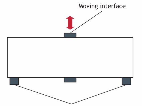
Amplified Actuators
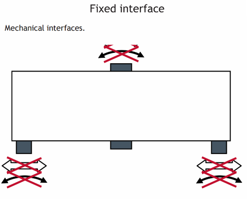
Amplified actuators provide two mechanical interfaces:
- Fixed interface: 2xM3
- Moving interface: 1xM3
Important
Please respect the maximum depth of 6mm for the fasteners.
When tightening a fastener on the moving interface, make sure that no torque is induced in the piezo stacks. Tighten the screw while holding the moving interface (7mm wide) using a wrench/spanner. When applying a force on the moving interface, be aware that the piezoelectric actuator may generate charge (i.e. voltage) during loading/unloading, so it should be connected to a load or properly discharged before connecting to electronics.
During assembly and operation, avoid additional stress on the actuator such as:
- Pushing/pulling and bending between the two points of the fixed interface.
- Transverse and bending the moving interface.
Learn more about our amplified actuator
Shear plates
Shear plate actuators present electrodes on top and bottom surfaces. They may be mounted either by mechanical clamping or with an adhesive.
In the case of clamping, axial stress on shear plate actuators must be controlled. Too low pressure can lead to slippage whereas too high pressure can damage the ceramic. . The substrate must be clean, flat (<10µm depending on dimensions) and smooth (Ra 1.6µm).With the appropriate contact surface and in the case of low shear force, a pressure of 1 to 3 MPa can be recommended.
The stiffness of the clamping mechanism in the actuation direction shall be as low as possible in order not to hinder the movement of the actuator.
The clamping force must be applied on the full surface of the actuator in order to ensure a good load distribution.
It can be necessary to insulate the contact surfaces from the rest of the structure. This can be achieved by adding inactive ceramic plates in the structure, or polyimide film insulator.
For bonding, we recommend to use a hard epoxy (Shore D 70-90). It is important to ensure a very thin glue line between the shear plate actuator and the substrate. This is generally achieved by using low viscosity epoxy. A pressure, e.g. 2-3 MPA, should be applied during the curing process.
Shear Stacks
Shear stacks are fitted with inactive ceramic end-plates on top and bottom surfaces as a standard in order to provide electrical insulation. The actuators may be mounted either by mechanical clamping or with an adhesive.
For clamping, most materials can be used, although materials with a high stiffness (steel, titanium) are preferred in order not to affect the overall stiffness of the system, i.e. its force generation capability. The substrate must be clean, flat (<10µm depending on dimensions) and smooth (Ra 1.6µm). The clamping force must be adapted to the load on the actuator. Usually for shear stacks, clamping pressures of 1-3MPa are sufficient. When applying a force, be aware that the Z section of a XYZ shear stack will generate charge (i.e. voltage) during loading/unloading, so the terminals must be connected to a resistor or shorted at all times.
The stiffness of the clamping mechanism in the actuation direction shall be as low as possible in order not to hinder the movement of the actuator.
For bonding, we recommend to use a hard epoxy (Shore D 70-90). It is important to ensure a very thin glue line between the shear plate actuator and the substrate. This is generally achieved by using low viscosity epoxy. A pressure, e.g. 2-3 MPA, should be applied during the curing process. When curing at elevated temperature, the Z section of a XYZ shear stack will generate charge (i.e. voltage) during temperature changes, so the terminals must be connected to a resistor or shorted at all times.
To avoid significant loss of performance, the mounting of the actuators should avoid mechanical clamping and/or bonding on the sides of the actuator.
Actuators without preload are sensitive to tensile stress. Pulling forces can be caused by the load on the actuator or by inertial load, i.e. deceleration of the own mass of the actuator in the case of actuation in Z direction. It is recommended to apply a pre-load in order to protect the actuators from tensile stress. In addition, preloading will increase the stiffness of the actuator and thereby optimize its dynamic performance.
The load must be applied on the full surface of the actuator in order to assure a good load distribution. Uneven loading can cause stress concentrations, leading to cracking. If this is not possible, an interface part must be used to help spread the load.
During manufacturing or handling, minor chips on the end-plates can appear. Minor chips (<5% of the edge size) cannot be avoided, but such chips do not affect performance. Larger chips can cause stress concentrations and initiate cracking under heavy loads.
Partner with a Piezoelectric Specialist
CTS can help decide on material properties to deliver products that meet the unique requirements of your project. Work with a technical expert to begin your design today.